Urethane Cast Figurine
Solidworks
3/05/24 - 3/26/24: Group of 2
Overview/Executive Summary
Final Urethane Mold
For this project, we designed and built a small product from which a stream of derivative future products could be efficiently developed and produced. This was done using liquid urethane that was pouring into a flexible silicone mold that was cured at room tempersutre. This allowed for cost effective small runs and design flexibility!
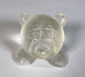
My partner and I decided to make a Kirby figurine. We made two copies, with the first being mostly successful other than airbubbles present in places that were highest in the cast. The second cast did not some out successful, however this was likely due to the liquid urethane ratio being incorrect.
Design
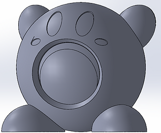
We found an image of Kirby online and recreated it using Solidworks to create the mold. Both partners contributed equally to the CAD.
Kirby Figure
We then added a part that would create the injection and vent holes and support the piece while it sat in the resin bin.


Vent Holes
Injection Gate
Kirby Figure w/ Injection and Vent Hole Marker
We placed our vent holes at the highest points of the piece, believing that air would naturally ride to those places and then escape. For the feet, we decided to place the vent hole underneath the feet so that it was easy to attached to the main body using super glue. Otherwise, it would be difficult to attach to a curved surface. For the injection hole, we chose to do the center of the mouth because it also served as a center point for the entire figure and would reach all points of the mold easiest this way.
Design for Manufacturing (DFM) Principles:
Because of the natural curvature of our workpiece, we did not put heavy consideration into draft angles. The curvature of our part would help in pulling apart the molds. Also due to the unique shape of our mold and the many angles and undercuts, we created a 3 part mold to avoid complications when pulling the final piece from the mold.
When using xometry.com to get an estimate of how much it would cost to produce our part, it came to about $374.88, which is a lot for just one small part. This is for a clear part with a hardness of Shore D 80 and matte finish.
Fabrication
After 3D printing our parts, we used these to create the mold.

Extra SIlicone Mold
To the left is a photo after we created our first part of the mold. We initially poured over our intended parting lineand despite pouring out the excess part ofthe silicone remained stuck to the perimeter of the 3D print. This can be seen to the left. This was fixed by removing the 3D print from the mold, cutting off the extra material that had cast around the surface of the 3D print, and then putting the 3D print back and resuming as normal.
Below are images showing the final 3 part mold and how we prepared it to then pour in the liquid urethane. To ensure that the mold pieces wouldn't shift and were aligned correctly we had registration pins (which in this case we used clay) and held it together with rubber bands. We then poured the liquid urethane in, trying to fill it to the bottom of the injection gate.


Our first mold came out successfullyy and photos can be found below of this. We had to file down certain areas such as the parting lines and where the vent holes were. Our second mold was an odd texture and was not completely solidified. This is likely due to incorrect ratios with the liquid urethane we mixed.

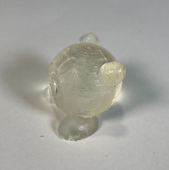

Various Angles of the Final Part

.png)
CADA Renderings of Kirby
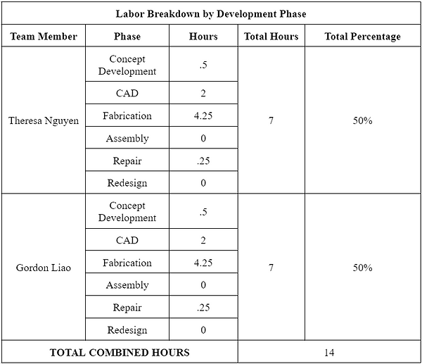
Team Contribution
All of the work was done jointly, with an exception of each team member doing one part of the mold alone.
Reflection
The result of our design was mostly successful. There were air bubbles present in our part, which could likely be resolved either by tapping the mold down on a table to force the air bubbles to the surface or putting the part in a pressure chamber. Regardless, the airbubbles are minor imperfections and our overall part came out as intended. Other potential revisions could be creating larger vent holes or testing out various locations for an optimal final product. I also wish we added coloring just so features could be more easily distinguished, such as the eyes. Our second part did not come out successful, with the plastic being an odd mush rather than a rigid material. It's possible that when mixing the liquid urethane, the ratios were incorrect, emphasizing how imporatnt tgetting this ratio correst is for a successful product.
However, the mold itself came out quite well. The placement of the parting lines was perfect to avoid undercuts, making it easy to remove the workpiece from the mold without damaging the mold. Despite the error with pouring too much silicone for our first mold, this was easily fixed by removing the 3D print from the mold, cutting off the extra material that had cast around the surface of the 3D print, and then putting the 3D print back and resuming as normal.
Conclusion
Our part came out successfully with our 3 -part mold! While the parting lines are somewhat oddly placed and not straight due to the mold not fully leveling out, our model also comes out smoothly and easily as long as the correct amount of urethane. I successfully learned how to make a silicone mold and a urethane part! I'm happy with how it came out and hope to make more of these soon.