Articulating Arm
to stabilize a probe used for early detection of cervical cancer
Metal Working
Group of 2: 9/12 - 12/10
WARNING: THIS PAGE IS A WORK IN PROGRESS
Overview/Motivation
Since the 1970s, there has been no improvement in the survival rate of cervical cancer in the US. These rates are likely worse in more underdeveloped nations and current cervical cancer screening tests are painful. Researchers in Tufts’ Biomedical Engineering Department have developed a probe that will use two-photon imaging for a less invasive method to detect early onset of cervical cancer. This probe needed an arm that could be easily adjusted by the clinician while maintaining a stable position so that no motion artifacts are present in the image.
WHY DID I PICK THIS PROJECT?
I'm really interested in pursuing medical devices following my undergraduate career and this was a great opportunity to further explore this interest. It presents opportunities to collaborate with clinicians and researchers in a professional setting and this project addresses inequities in women's health, which I believe needs to gain more attention.
Exploring Clinician and Patient Needs
We had the opportunity to speak with a gynecologist from Tufts Medical Center to understand her needs as a user of the product. We visited her office and determined a a variety of user needs, some of which included:

These user needs translated to engineering requirements, which included:
-
Stability within at least 0.05 mm (50 microns)
-
Achieve at least 5 degrees of freedom
-
Materials Standard: Multiple-use parts that may come in contact with the patient must be made from stainless steel AISI 301, 302, 303, 304, 305, 316, or 317 to match sterilization and corrosion-resistance standards of non-implant medical devices and dental appliances
-
The arm will not apply any additional pressure onto the patient or touch the patient directly
-
Must not obscure the clinician’s view
Design and Ideation
.jpeg)
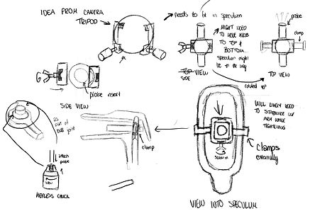
Idea Inspired by Camera Tripod
After speaking with other mechanical engineers, clinicians, and our team of researchers it was time to brainstorm ideas! We had each group member come up with a few sketches and ideas and then we would come together to discuss and collaborate, combining parts of ideas when necessary. To the left was one of my ideas which was inspired by the use of a ball and socket joint commonly found in camera tripods.
An idea that our group had for awhile that we were discussing was whether to attach our device to the speculum or to the colposcope, which are both devices commonly used in gynecology offices and in cervical biopsies. My design on the left is based on using the speculum.
In order to unbiasely decide what we wanted to use as a base for our product, we used a decision matrix. It resulted in us using a colposcope attachment, primarily because the colposcope is adaptable to all office settings and wouldn't add extra discomfort to the patient (unlike a speculum).

From all of our design concepts, we identified a list of morphologies that we could implement in our design. The ones highlighted were the ones used in our final design.

Final Design
The final design concept chosen for our prototype is heavily inspired by balanced-arm lamps. Balanced-arm lamps can be found in everyday life and are easily adjustable, relying on springs to retain position.

Side View and Third Angle View of Final Design CAD
We heavily referenced a paper by M.J. French which utilized statics analysis to achieve a stable arm position. We were then able to use the equations presented in the paper to calculate the required spring constants we would need to maintain a stable position. Accounting for the friction and counterbalance provided by the nuts and connections of each joint, we purchased springs with stiffness coefficients less than those that we calculated.
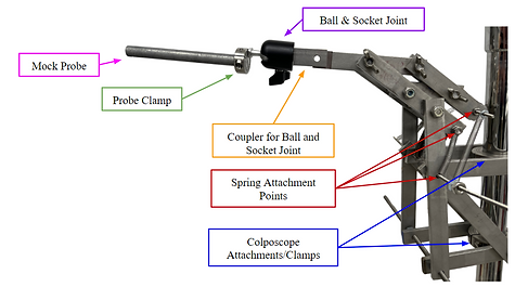
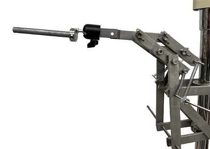
Third Angle View of the Final Prototype
oOur team originally hoped to use a gooseneck to provide 6 degrees of freedom. However, after purchasing several goosenecks, we determined that goosenecks vary too largely in terms of rigidity. Therefore, we switched to a ball and socket joint attachment to provide the additional degrees of freedom we needed.

Because we decided to incorporate a ball and socket joint later in our fabrication process, we had to create a way to attach it to the end of the moving arm mechanism. After discussion and consultation with several engineers, we manufactured a coupler to attach the two parts together.
Exploded View of Coupler, Ball-and-Socket Joint, and Probe Clamp
Manufacturing
To manufacture our device, we used the metal working shop at Tufts. I was super excited to learn to use machines that I was unfamiliar with, such as the mill!
For most of our parts, we were able to use a vertical bandsaw to cut rods into our required lengths. Additionally, we used a drill press to drill the holes inside. The mill was mainly used for making the custom parts such as the coupler!
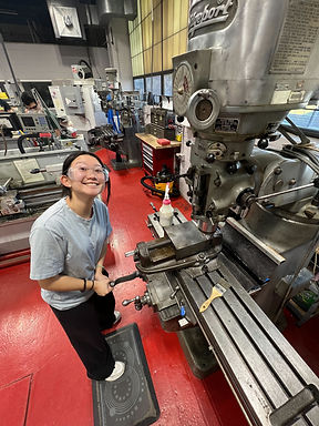
Using the Mill to Create the Coupler
Design Validation/Testing
To conduct testing on how well our prototype met our engineering requirements, we used Logger Pro. The main things we wanted to test were range of motion and stability.
RANGE OF MOTION
We captured images of the probe at maximum and minimum stable limits. The distance from the base of the arm to the end of the probe was calculated for each image using Logger Pro. Each image represented a translational extreme: z-max, z-min, x-max, and x-min. The probe has no y-translation and that requirement is instead covered by the rotational motion around y.


STABILITY

Three operational positions were evaluated to see if the stability is satisfied through a range of arm positioning. The actuating arm must provide stability within a range of 50 microns for accurate images of the cervix, free from motion artifacts. To measure the total movement of the probe when at three different positions we used LoggerPro to analyze 4k zoomed videos of the probe over 5 seconds. We calibrated the video dimensions by placing a 5 mm thick red tape on the probe.
Conclusion
Our prototype fulfilled most of the requirements that we outlined: achieving stability within 50 microns, achieving a large range of motion, and being compatible with all gynecology offices via connection to a colposcope!
Limitations
-
The majority of the parts are made of stainless steel, but we were unable to find or manufacture complex parts, such as the ball-and-socket joint, entirely of stainless steel. Aluminum is also wisely used in medical settings, so although we believe the parts may still be compatible in medical settings, we could not find standards for aluminum.
-
The x-range of the arm did not meet our engineering requirements.
Future Revisions
-
Adding handles so the clinician can adjust the probe easily from behind the colposcope
-
Reduce the number of springs by calculating the required spring coefficients with trial and error
-
Using shorter springs would also allow the prototype to maintain its position in more orientations because longer springs may not provide a counterbalancing force in certain orientations
-
Incorporating a method to cover the springs for aesthetic purposes
-
Slightly modifying the design so that the springs do not contact undesired parts such as the beams or hex nuts, possibly by extending the threaded rods outward and making the overall design wider